|
目录
一,产品概述(General Description)

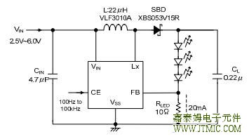
The JTMT9133 series is a fixed frequency, constant current step-up DC/DC converter which is optimized for LED backlight,
applications in mobile phones, PDAs and digital cameras. Output voltage of up to 17.5V is possible so that four white LEDs,can be
driven in series. Since the LED current is set by only one external resisto.all white LEDs placed in series can be turned,on at the
same time. The new DC/DC Converter is also able to drive a network of two parallel banks of three LEDs. LED dimming is
controlled by adjusting the duty cycle of a PWM signal (10kHz Max.) applied to the CE pin.Efficiency is high with a 0.2V low feedback
reference voltage ensuring the RLED losses are minimal. In addition, an internal,MOSFET with a low RDSON of 2.4Ω is used. A low
profile and small board area solution can be achieved using a chip inductor,and a small ceramic output capacitor CL=0.22μF as
a result of the high 1MHz switching frequency.
If white LEDs are opened or damaged, the detector built in the Lx pin causes the IC to stop oscillating, preventing eJTMTessive
,increase of the output voltage.
二.产品特点(Features)
|
Input Voltage Range |
2.5V~6.0V |
|
Output Voltage Range |
Up to 17.5V externally set-up, Reference voltage 0.2V +5% |
|
Oscillation Frequency |
1.0MHz±20% |
|
ON Resistance |
2.4Ω |
|
High Efficiency |
85%, 3 white LEDs in series, VIN=3.6V, ILED=20mA |
|
Control |
PWM control |
|
Stand-by Current |
ISTB=1.0μA (MAX.) |
|
Output Capacitor |
0.22μF, ceramic |
|
Lx Limit Current |
360mA(TYP.) |
|
Lx Overvoltage Limit |
19V (TYP.) |
|
Packages |
SOT-25 |
三,应用范围 (Applications)
●For White LED drivers
●Smart phones / Mobile phones
●Mobile devices / terminals
●Digital still cameras
四.技术规格书下载(产品PDF)
五,产品封装图 (Package)
六.电路原理图
七,功能概述
|
PARAMETER |
SYMBOL |
RATINGS |
UNITS |
|
VIN Pin Voltage |
VIN |
VSS – 0.3 ~ 7.0 |
V |
|
Lx Pin Voltage |
VLx |
VSS – 0.3 ~ 22.0 |
V |
|
FB Pin Voltage |
VFB |
VSS – 0.3 ~ 7.0 |
V |
|
CE Pin Voltage |
VCE |
VSS – 0.3 ~ 7.0 |
V |
|
Lx Pin Current |
ILx |
1000 |
mA |
|
Power Dissipation |
Pd |
250 |
mW |
|
Operating Ambient Temperature |
Topr |
- 40 ~ + 85 |
℃ |
|
Storage Temperature |
Tstg |
- 55 ~ +125 |
℃ |
八,相关芯片选择指南
|
系列名称 |
特点 |
输入电压 |
输出电压 |
最大输出电流 |
振荡频率 |
内置FET |
封装 |
|
(V) |
(V) |
(mA) |
|
最小 |
最大 |
最小 |
最大 |
|
|
JTMT6367 |
PWM/PFM |
0.9 |
10 |
1.5 |
6.5 |
1000 |
100kHz |
None |
SOT-25 |
|
JTMT6368 |
180kHz |
|
|
300kHz |
|
|
500kHz |
|
JTMT6371 |
PWM/PFM |
0.9 |
10 |
2 |
7 |
100 |
50kHz |
Nch FET |
SOT-89 |
|
JTMT6372 |
100kHz |
SOT-89-5 |
|
|
180kHz |
USP-6B |
|
JTMT9101 |
PWM |
2.5 |
20 |
2.2 |
30 |
1500 |
100~600kHz |
None |
MSOP-8A |
|
JTMT9103 |
PWM/PFM |
0.9 |
10 |
1.5 |
30 |
1000 |
100kHz |
None |
SOT-25 |
|
JTMT9104 |
180kHz |
USP-6B |
|
JTMT9105 |
300kHz |
|
|
|
500kHz |
|
|
JTMT9106 |
PWM/PFM |
0.9 |
10 |
1.5 |
30 |
1000 |
100kHz |
None |
SOT-25 |
|
JTMT9107 |
300kHz |
USP-6B |
|
JTMT9110 |
PFM |
0.9 |
10 |
1.5 |
7 |
100 |
100kHz |
Nch FET |
SOT-23 |
|
JTMT9111 |
SOT-25 |
|
|
SOT-89 |
|
|
USP-6C |
|
JTMT9116 |
Backlight LED Driver |
2.5 |
6 |
8 |
18 |
20 |
1MHz |
Nch FET |
SOT-25 |
|
USP-6B |
|
JTMT9119 |
PWM |
2.5 |
6 |
10 |
18 |
100 |
1MHz |
Nch FET |
SOT-25 |
|
USP-6C |
|
JTMT9120 |
PWM/PFM |
0.9 |
6 |
1.5 |
30 |
80 |
100kHz |
None |
SOT-25 |
|
JTMT9121 |
USP-6C |
|
JTMT9122 |
|
|
JTMT9128 |
1A Driver Transistor Built-In |
0.8 |
6 |
1.8 |
5.3 |
500 |
1.2MHz |
Nch FET |
MSOP-10 |
|
JTMT9129 |
Pch FET |
USP-10B |
|
JTMT9131 |
Load Disconnection Function |
0.65 |
5.5 |
1.8 |
5 |
500 |
1.2MHz |
Nch FET |
USP-10B |
|
Pch FET |
|
JTMT9133 |
LED Backlight |
2.5 |
6 |
2.5 |
17.5 |
20 |
1MHz |
MOSFET |
SOT-25 |
|
JTMT9135 |
1A Driver Transistor Built-In |
0.65 |
5.5 |
1.8 |
5 |
500 |
1.2MHz |
Nch FET |
USP-10B |
|
JTMT9136 |
Pch FET |
|
JTMT9140 |
Synchronous PFM |
0.9 |
5.5 |
1.8 |
5 |
100 |
- |
N-ch Driver Tr |
SOT-25 |
|
P-ch Synchronous Switch Transistor |
USP-6EL |
|
JTMT9141 |
Load Disconnection Function |
0.65 |
6 |
1.8 |
5.5 |
350 |
1.2MHz |
Nch FET |
SOT-25 |
|
JTMT9142 |
3.0MHz |
Pch FET |
USP-6C |
|
|
|
|
WLP-6-01 |
(责任编辑:oumao18) |


 粤ICP备13004986号-3