|
目录
一,产品概述(General Description)

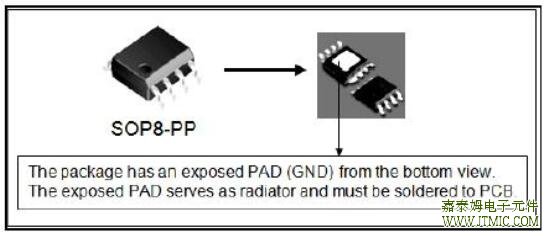
The TD2778 is a monolithic synchronous buck regulator. The device integrates two 90mΩ MOSFETs, and provides2.2A of continuous load current over a wide input voltage of 4.75V to 37V.Current mode control provides fast transient response and cycle-by-cycle current limit.An adjustable soft-start prevents inrush current at turn-on, and inshutdown mode the supply current drops to 1µA.This device, available in an SOP8-PP package, provides a verycompact solution with minimal external components
二.产品特点(Features)
* 2.2A Output Current
* Wide 4.75V to 32V Operating Input Range
* Integrated 90mΩ Power MOSFET Switches
* Output Adjustable from 0.923V to 30V
* Up to 93% Efficiency
* Programmable Soft-Start
* Stable with Low ESR Ceramic Output Capacitors
* Fixed 200KHz Frequency
* Cycle-by-Cycle Over Current Protection
* Input Under Voltage Lockout
三,应用范围 (Applications)
* Distributed Power Systems
* Networking Systems
* FPGA, DSP, ASIC Power Supplies
* Green Electronics/ Appliances
* Notebook Computers
四.技术规格书下载(产品PDF)
五,产品封装图 (Package)

|
Pin Number |
Pin Name |
Description |
|
1 |
BS |
High-Side Gate Drive Boost Input. BS supplies the drive for the high-side N-Channel
MOSFET switch. Connect a 0.01µF or greater capacitor from SW to BS to power the
high side switch. |
|
2 |
IN |
Power Input. IN supplies the power to the IC, as well as the step-down converter
switches. Drive IN with a 4.75V to 32V power source. Bypass IN to GND with a
suitably large capacitor to eliminate noise on the input to the IC. See Input Capacitor. |
|
3 |
SW |
Power Switching Output. SW is the switching node that supplies power to the output.
Connect the output LC filter from SW to the output load. Note that a capacitor is
required from SW to BS to power the high-side switch. |
|
4 |
GND |
Ground. |
|
5 |
FB |
Feedback Input. FB senses the output voltage to regulate that voltage. Drive FB
with a resistive voltage divider from the output voltage. The feedback threshold
is 0.923V. See Setting the Output Voltage. |
|
6 |
COMP |
Compensation Node. COMP is used to compensate the regulation control loop.
Connect a series RC network from COMP to GND to compensate the regulation
control loop. In some cases, an additional capacitor from COMP to GND is
required. See Compensation Components. |
|
7 |
EN |
Enable Input. EN is a digital input that turns the regulator on or off. Drive EN high to
turn on the regulator, drive it low to turn it off. Pull up with 100kΩ resistor for
automatic startup. |
|
8 |
SS |
Soft-Start Control Input. SS controls the soft start period. Connect a capacitor from SS
to GND to set the soft-start period. A 0.1µF capacitor sets the soft-start period to 15ms.
To disable the soft-start feature, leave SS unconnected. |
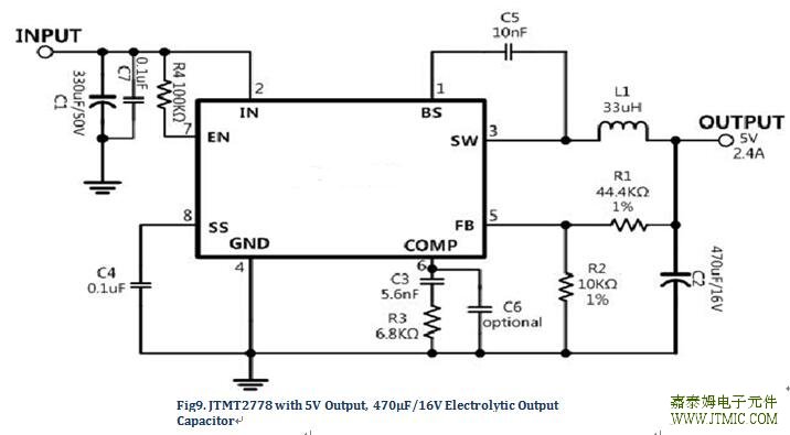
六.电路原理图
七,功能概述
|
Parameters |
Symbol |
Test Condition |
Min. |
Typ. |
Max. |
Unit |
Input Under Voltage Lockout
Threshold |
|
VIN Rising |
3.80 |
4.10 |
4.40 |
V |
Input Under Voltage Lockout
Threshold Hysteresis |
|
|
|
210 |
|
mV |
|
Soft-Start Current |
|
VSS = 0V |
|
6 |
|
µA |
|
Soft-Start Period |
|
CSS = 0.1µF |
|
15 |
|
ms |
*
Thermal Shutdown |
|
|
|
160 |
|
°C |
八,相关芯片选择指南
(责任编辑:oumao18) |


 粤ICP备13004986号-3