


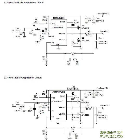
六.电路原理图
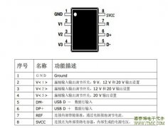
七,功能概述
Output Capacitor Selection
The selection of COUT is determined by the required effec-tive series resistance (ESR) and voltage
rating rather than the actual capacitance requirement. Therefore, selecting high performance low ESR
capacitors is intended for switching regulator applications. In some applications,multiple capacitors have
to be paralleled to achieve the desired ESR value. If tantalum capacitors are used, make sure they are
surge tested by the manufactures. If in doubt,consult the capacitors manufacturer.
Input Capacitor Selection
The input capacitor is chosen based on the voltage rat-ing and the RMS current rating. For reliable operation,
select the capacitor voltage rating to be at least 1.3 times higher than the maximum input voltage. The maximum
RMS current rating requirement is approximately IOUT/2 where IOUT is the load current. During power up, the
input capacitors have to handle large amount of surge current.If tantalum capacitors are used, make sure they
are surge tested by the manufactures. If in doubt, consult the ca-pacitors manufacturer.For high frequency
decoupling, a ceramic capacitor be-tween 0.1µF to 1µF can connect between VCC and ground pin.
Inductor Selection
The inductance of the inductor is determined by the out-put voltage requirement. The larger the inductance, the
lower the inductor’s current ripple. This will translate into lower output ripple voltage. The ripple current and ripple
voltage can be approximated by:
× OUT
FSW × L VIN
where Fs is the switching frequency of the regulator.
∆VOUT = IRIPPLE x ESR
A tradeoff exists between the inductor’s ripple current and the regulator load transient response time. A smaller in-
ductor will give the regulator a faster load transient re-sponse at the expense of higher ripple current and vice
versa. The maximum ripple current occurs at the maxi-mum input voltage. A good starting point is to choose the
ripple current to be approximately 30% of the maximum output current.Once the inductance value has been chosen, selecting an inductor is capable of carrying the required peak cur-rent without going into saturation. In some types of
inductors, especially core that is make of ferrite, the ripple current will increase abruptly when it saturates. This will
result in a larger output ripple voltage.
Compensation
The output LC filter of a step down converter introduces a double pole, which contributes with -40dB/decade gain
slope and 180 degrees phase shift in the control loop. A compensation network between COMP pin and ground
should be added. The simplest loop compensation net-work is shown in Figure 5.
The output LC filter consists of the output inductor and output capacitors. The transfer function of the LC filter is
given by:
The FLC is the double poles of the LC filter, and FESR is the zero introduced by the ESR of the output capacitor.
 Allegro 的 ACS726 电流传感器
人气:216
Allegro 的 ACS726 电流传感器
人气:216
 The JTM3410D is a constant freq
人气:195
The JTM3410D is a constant freq
人气:195
 SFL710是针对Buck架构优化的
人气:193
SFL710是针对Buck架构优化的
人气:193
 NUP45V6、NUP46V8和NUP412V全球
人气:183
NUP45V6、NUP46V8和NUP412V全球
人气:183
 内置高低压过流补偿实现
人气:182
内置高低压过流补偿实现
人气:182
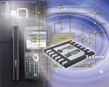 双通道AAT1270采用一个带小
人气:163
双通道AAT1270采用一个带小
人气:163
 JTM6283B是一款升压恒流型
人气:160
JTM6283B是一款升压恒流型
人气:160
 ADF5904 接收器降频转换器
人气:158
ADF5904 接收器降频转换器
人气:158
 JM100支持 QC2.0 协议的低成
人气:132
JM100支持 QC2.0 协议的低成
人气:132
 自动补偿输入电压,电感
人气:131
自动补偿输入电压,电感
人气:131
 粤ICP备13004986号-3