|
六.电路原理图 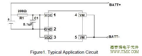 七,功能概述
TheJTM5418series monitors the voltage and current of a battery and protects it from begin
damaged due to overcharge voltage, over discharge voltage, over discharge current, and short
circuit conditions by disconnecting the battery from the load or charger. These functions are required in order to operate the battery cell within specified limits. The device requires only one external capacitor. The MOSFET in integrated and has a low Equivalent RdSon of 50mojtm.
The JTM5418 series supports four operating modes: normal, discharge, charge, and low power.
Normal operating mode
If no exception condition is detected, charging and discharging can be carried out freely. This condition is called the normal operating mode. Over charge voltage condition When the battery voltage becomes higher than the overcharge detection voltage during charging under the normal condition and the detection continues for a period equal to overcharge
voltage detection delay time or longer, the JTM5418 series will control the internal MOSFET to stop
charging. This condition is called the overcharge voltage condition. If the error condition clearswithin overcharge voltage detection delay time, no action will be taken. The overcharge condition is released by the following two events: (1) When the battery voltage drops below the overcharge release voltage (VCL), the turns the charging control FET on and returns to the normal condition. (2) When a load is connected and discharging starts, the JTM5418
turns the charging control FET on and returns to the normal condition.
Over charge current condition While operating in the charge condition, if current exceeds IOCC and it continues for overcharge current detection delay time or longer, the IC will control the internal MOSFET to stop charging. This situation is called overcharge current condition.
The JTM5418 series continuously monitors current and will release the overcharge current
condition as soon as the voltage of VM pin is equal or lower than voltage of VDD pin by connecting
an external load which is already connected to battery pack or charger is removed. Over-discharge voltage condition When battery voltage falls below over discharge detection voltage during discharging under normal condition and detection continues for over discharge detection delay time or longer, the JTM5418 series disconnects the battery from the load to stop further discharging. This situation is called over discharge voltage condition. When discharge control MOSFET is turned off, VM pin voltage is pulled down by a resistor between VM and GND in the IC. When voltage difference between VM and GND is 1.5V (typical) or lower, current consumption is reduced to power-down current consumption. This situation is called the power-down condition. The power-down condition is released when a charger is connected and voltage difference between pin VM and GND becomes 2.0V or higher. Additionally, when the battery voltage equals
the over discharge detection voltage or is higher, the JTM5418 series returns to the normal condition. Over-discharge Current Condition (Detection of Over-discharge current1, Over-discharge current 2) If discharge current exceeds the specified value and condition lasts for over-discharge current detection delay time, battery is disconnected from load. If current drops again below specified value during delay time, no actions will be taken. The over-discharge current status is reset when impedance between VM pin and GND increases and is equal to or higher than impedance that enables automatic restoration to normal status. Disconnecting load surely restores to normal status from over-discharge current condition. Load Short-circuiting condition If voltage of VM pin is equal or below short circuiting protection voltage, the IC will stop discharging and battery is disconnected from load. The maximum delay time to switch current off is TSHORT. This status is released when voltage of VM pin is higher than short protection voltage, (责任编辑:oumao18) |

 粤ICP备13004986号-3