六.电路原理图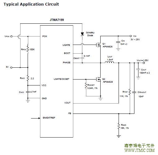 七,功能概述 Constant-On-Time PWM Controller with Input Feed-For-ward The constant-on-time control architecture is a pseudo-fixed frequency with input voltage feed-forward. This ar- chitecture relies on the output filter capacitor’s effective series resistance (ESR) to act as a current-sense resis- tor so the output ripple voltage provides the PWM ramp signal. In PFM operation, the high-side switch on-time is controlled by the on-time generator is determined solely by a one-shot whose pulse width is inversely propor- tional to the input voltage and directly proportional to the output voltage. In PWM operation, the high-side switch on-time is determined by a switching frequency control circuit in the on-time generator block.The switching frequency control circuit senses the switch-ing frequency of the high-side switch and keeps regulat- ing it at a constant frequency in PWM mode. The design improves the frequency variation and is more outstand- ing than a conventional constant-on-time controller, which has large switching frequency variation over input voltage, output current, and temperature. Both in PFM and PWM,the on-time generator, which senses input voltage on PHASE pin, provides very fast on-time response to input line transients. Another one-shot sets a minimum off-time (typical:300ns). The on-time one-shot is triggered if the error com- parator is high, the low-side switch current is below the current-limit threshold, and the minimum off-time one- shot has timed out. Pulse-Frequency Modulation (PFM) In PFM mode, an automatic switchover to pulse-frequency modulation (PFM) takes place at light loads. This switchover is affected by a comparator that truncates the low-side switch on-time at the inductor current zero crossing. This mechanism causes the threshold between PFM and PWM operation to coincide with the boundary between continuous and discontinuous inductor-current operation (also known as the critical conduction point). The on-time of PFM is given by: Ultrasonic Mode The ultrasonic mode activates an unique PFM mode with a minimum switching frequency of 20kHz. The minimum frequency 20kHz of ultrasonic mode eliminates audio-frequency interference in light load condition. It will transit to unique PFM mode when output loading makes the frequency bigger than ultrasonic frequency. In ultrasonic mode, the controller automatically transits to fixed-frequency PWM operation when the load reaches the same critical conduction point (ILOAD(PFM to PWM)).When the controller detects that no switching has oc- curred within about 40µs (Typical), an ultrasonic pulse will be occurred. The ultrasonic controller turns on the low-side MOSFET firstly to reduce the output voltage. After feedback voltage drops below the internal reference voltage, the controller turns off the low-side MOSFET and triggers a constant-on-time. When the constant-on-time has expired, the controller turns on the low-side MOSFET again until the inductor current is below the zero-cross- ing threshold. The behavior is the same as PFM mode. Power-On-Reset (POR) A Power-On-Reset (POR) function is designed to prevent wrong logic controls when the VCC voltage is low. The POR function continually monitors the bias supply volt-age on the VCC pin if at least one of the enable pins is set high. When the rising VCC voltage reaches the rising POR voltage threshold (4.2V, typical), the POR signal goes high and the chip initiates soft-start operations. When this voltage drops lower than 4.0V (typical), the POR dis- ables the chip. (责任编辑:oumao18) |

 粤ICP备13004986号-3