|
目录
一,产品概述(General Description) The JTM3019 IS step-up DC/DC converters designed to drive up to six LEDs in series from a Li-Ion cell.Series connection of the LEDs provides identical LED currents and eliminates the need for ballast resistors.These devices integrate the Schottky diode required exter-nally on competing devices. Additional features include output voltage limiting when LEDs are disconnected, one-pin shutdown and dimming control. The JTM3109 has internal soft-start. The JTM3019 switches at 1.2MHz, allowing the use of tiny external components. Constant frequency switching results in low input noise and a small output capacitor.Just 0.22µF is required for 4-, 6- or 8-LED applications. The JTM3019 is available in low profile(1mm)6-lead 二.产品特点(Features) Inherently Matched LED Current Drives Up to 8 LEDs from a 3.6V Supply No External Schottky Diode Required 1.2MHz Switching Frequency Automatic Soft-Start Open LED Protection High Efficiency: 81% Requires Only 0.22mF Output Capacitor Low Profile (1mm) SOT-23 Packaging 三,应用范围 (Applications) Cellular Phones PDAs, Handheld Computers Digital Cameras MP3 Players GPS Receivers 四.下载产品资料PDF文档
五,产品封装图 (Package) 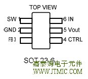 六.电路原理图 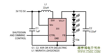 七,功能概述 The JTM3019 uses a constant frequency, current mode control scheme to provide excellent line and load regula- tion. Operation can be best understood by referring to the block diagram in Figure 2. At the start of each oscillator cycle, the SR latch is set, which turns on the power switch Q1. A voltage proportional to the switch current is added to a stabilizing ramp and the resulting sum is fed into the positive terminal of the PWM comparator A2. When this voltage exceeds the level at the negative input of A2, the SR latch is reset turning off the power switch. The level at the negative input of A2 is set by the error amplifier A1, and is simply an amplified version of the difference (责任编辑:oumao18) |


 粤ICP备13004986号-3