


目录
一,产品概述(General Description)
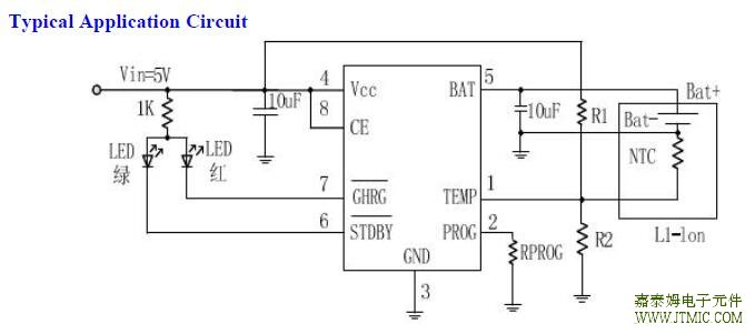
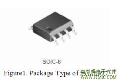
The JTM5056 is a complete constant current & constant voltage linear charger for single cell lithium-ion batteries.Its SOP package and low external component count make the JTM5056 ideally suited for portable applications.
Furthermore, the JTM5056 is specifically designed to work within USB power specifications.No external sense resistor is needed, and no blocking diode is required due to the internal MOSFET architecture. Thermal feedback regulates the charge current to limit the die temperature during high power operation or high ambient temperature. The charge voltage is fixed at 4.2V, and the charge current can be programmed externally with a single resistor. The JTM5056 automatically terminates the charge cycle when the charge current drops to 1/10th the programmed value after the final float voltage is reached.When the input supply (wall adapter or USB supply) is removed, the JTM5056 automatically enters a low current state, dropping the battery drain current to less than 2uA.
The JTM5056 can be put into shutdown mode, reducing the supply current to 50uA.Other features include Battery temperature monitor,under-voltage lockout, automatic recharge and two status pins to indicate charge and charge termination.
二.产品特点(Features)
1.)No MOSFET, Sense Resistor or Blocking Diode Required
2.) Constant-Current/Constant-Voltage Operation with Thermal
Regulation to Maximize Charge Rate Without Risk of
Overheating
3.) Charges Single Cell Li-Ion Batteries Directly from USB Port
4.)Preset 4.2V Charge Voltage with ±1% Accuracy
5.)Charge Current Monitor Output for Gas Gauging
6.) Automatic Recharge
7.) Charge state pairs of output, no battery and fault status display
8.) C/10 Charge Termination
9.)50uA Supply Current in Shutdown
10.) 2.9V Trickle Charge Threshold
11.) Soft-Start Limits Inrush Current
12.) Battery temperature monitoring function
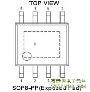
13.)Available in SOP8-PP Package
14.) Complete Linear Charger in SOP Package for single
Cell Lithium-Ion Batteries
三,应用范围 (Applications)
Cellular Telephones, PDAs, MP3 /MP4 Players
Charging Docks and Cradles
Bluetooth 、GPS Applications
四.下载产品资料PDF文档
 |
JTM5056 |
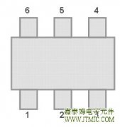
五,产品封装图 (Package)
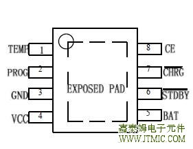
| Pin Number | Pin Name |
| 1 | TEMP |
| 2 | PROG |
| 3 | GND |
| 4 | VCC |
| 5 | BAT |
| 6 | STDBY |
| 7 | CHRG |
| 8 | CE |
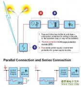
六.电路原理图
七,功能概述
Pin Function
TEMP (Pin 1): Battery temperature detection input. TEMP pin to receive the battery NTC sensor output. If the TEMP
pin voltage is less than the input voltage is greater than 45% or 80% of the input voltage means the battery temperature
is too low or too high, then the charge has been suspended.
If the TEMP direct access GND, battery temperature detection canceled, the other charged and functioning properly.
PROG (Pin 2): Charge Current Program, Charge Current Monitor and Shutdown Pin. The charge current is
programmed by connecting a 1% resistor, RPROG, to ground. When charging in constant-current mode, this pin servos
to 1V. In all modes, the voltage on this pin can be used to measure the charge current using the following formula:
IBAT = (VPROG/RPROG) ·1000
The PROG pin can also be used to shut down the charger. Disconnecting the program resistor from ground allows a 3uA
current to pull the PROG pin high. When it reaches the 1.21V shutdown threshold voltage, the charger enters shutdown
mode, charging stops and the input supply current drops to 50uA. This pin is also clamped to approximately 2.4V.
Driving this pin to voltages beyond the clamp voltage will draw currents as high as 1.5mA. Reconnecting RPROG to
ground will return the charger to normal operation.
GND (Pin 3): Ground.
VCC (Pin 4): Positive Input Supply Voltage. Provides power to the charger, VCC can range from 4.25V to 6.5V and
should be bypassed with at least a 10uF capacitor. When VCC drops to within 30mV of the BAT pin voltage, the
JTM5056 enters shutdown mode, dropping IBAT to less than 2uA.
BAT (Pin 5): Charge Current Output. Provides charge current to the battery and regulates the final float voltage to
4.2V. An internal precision resistor divider from this pin sets the float voltage which is disconnected in shutdown mode
.
STDBY (Pin 6): The completion of battery charging instructions side. When the battery charge is complete, STDBY
pulled low by internal switches, indicating the completion of charging. In addition, STDBY pin will be in a
high-impedance state.
CHRG (Pin 7): Open-Drain Charge Status Output. When the battery is charging, the CHRG pin is pulled low by an
internal N-channel MOSFET. When the charge cycle is completed, a weak pull-down of approximately 20uA is
connected to the CHRG pin, indicating an “AC present”condition. When the
condition, CHRG is forced high impedance.
056 detects an under voltage lockout
condition, CHRG is forced high impedance.
056 detects an under voltage lockout
CE (Pin 8): Chip enable input..High input level would
JTM5056 is in normal working condition; low input level so that
JTM5056 is prohibited charging status. CE pin can be TTL or CMOS level-level driver.
八,相关产品
| 同步整流3合1移动电源IC: | |||||||||||
| 型号 | 功能 | 包含的模块 | 工作模式 | 最低放 | 放电过 | 充电电流 | 升压 | 待机 | 0V电 | 保护功能 | 封装形式 |
| 电电压 | 流保护 | 效率 | 功耗 | 池充电 | |||||||
| JTM5903 | 0.8A 充电 | 充电模块 | 充电 | 2.85V | 0.8A | 88% | 20uA | 电池过充 | ESOP-8 | ||
| 同步1A 放电 | 升压电源模块 | 放电 | 过放保护 | ||||||||
| 移动电源 | 电量显示模块 | 首次充电 | 欠压保护 | ||||||||
| 管理IC | 以及保护模块 | 故障 | 芯片过温保护 | ||||||||
| 过流保护 | |||||||||||
| 短路保护 | |||||||||||
| JTM5913 | 0.6A 充电 | 充电管理模块 | 充电 | 2.85V | 0.6A | 90% | 20uA | 电池过充 | SOP-8 | ||
| 同步0.8A 放电 | 电量检测及 | 放电 | 过放保护 | ||||||||
| 移动电源 | 电量指示模块 | 待机 | 欠压保护 | ||||||||
| 管理IC | 升压放电管理模块 | 芯片过温保护 | |||||||||
| 过流保护 | |||||||||||
| 短路保护 | |||||||||||
| JTM5923 | 0.8A 充电 | 锂电充电模块 | 充电 | 2.85V | 0.8A | 90% | 20uA | 电池过充 | ESOP-8 | ||
| 同步1A 放电 | 升压电源模块 | 放电 | 过放保护 | ||||||||
| 三合一移动 | 综合控制模块 | 待机 | 过压保护 | ||||||||
| 电源管理IC | 保护模块 | 过载保护 | |||||||||
| 短路保护 | |||||||||||
| JTM5911 | 1.2A 充电 | 充电管理模块 | 充电 | 2.9V | 通过电阻调节 | 93% | 10uA | 电池过充 | SOP-16 | ||
| 同步1.5A 放电 | 电量检测及 | 放电 | 过放保护 | ||||||||
| 全集成移动 | 电量指示模块 | 待机 | 欠压保护 | ||||||||
| 电源管理IC | 升压放电管理模块 | 芯片过温保护 | |||||||||
| 过流保护 | |||||||||||
| 短路保护 | |||||||||||
| JTM5912 | 1.2A 充电 | 充电管理模块 | 充电 | 2.9V | 通过电阻调节 | 93% | 10uA | 电池过充 | ESOP-16 | ||
| 同步2A 放电 | 电量检测及 | 放电 | 过放保护 | ||||||||
| 全集成移动 | 电量指示模块 | 待机 | 欠压保护 | ||||||||
| 电源管理IC | 升压放电管理模块 | 芯片过温保护 | |||||||||
| 过流保护 | |||||||||||
| 短路保护 | |||||||||||
| JTM5915 | 1.2A 充电 | 充电管理模块 | 充电 | 3.0V | 通过电阻调节 | 91% | 50uA | 电池过充 | SOP-16 | ||
| 1A 放电 | 电量检测模块 | 放电 | 过放保护 | ||||||||
| 全集成 | 电量指示模块 | 待机 | 欠压保护 | ||||||||
| 移动电源管理IC | 升压放电管理模块 | 芯片过温保护 | |||||||||
| 过流保护 | |||||||||||
| 过压保护 | |||||||||||
| 短路保护 | |||||||||||
| JTM5918 | 2.5A 充电 | 充电管理模块 | 充电 | 3.0V | 通过电阻调节 | 95% | 50uA | 电池过充 | ESOP-16 | ||
| 2A 放电 | 电量检测模块 | 放电 | 过放保护 | ||||||||
| 全集成 | 电量指示模块 | 待机 | 欠压保护 | ||||||||
| 移动电源管理IC | 升压放电管理模块 | 芯片过温保护 | |||||||||
| 过流保护 | |||||||||||
| 过压保护 | |||||||||||
| 短路保护 | |||||||||||
| JTM5919 | 3A 充电 | 充电管理模块 | 充电 | 3.0V | 通过电阻调节 | 95% | 50uA | 电池过充 | QFN-24 | ||
| 2.4A 放电 | 电量检测模块 | 放电 | 过放保护 | ||||||||
| 移动电源管理IC | 电量指示模块 | 待机 | 欠压保护 | ||||||||
| 升压放电管理模块 | 芯片过温保护 | ||||||||||
| 过流保护 | |||||||||||
| 过压保护 | |||||||||||
| 短路保护 | |||||||||||
| JTM5908 | 扩流开关2A充电 | 锂电充电模块 | 充电 | 2.8V | 95% | 26uA | 过流(OCP)保护 | SOP-16 | |||
| 扩流同步2A放电 | 升压电源模块 | 放电 | 过压(OVP)保护 | ||||||||
| 三合一移动 | 电量显示模块 | 待机 | 短路(SCP)保护 | ||||||||
| 电源管理IC | 综合控制模块 | 欠压保护 | |||||||||
| 型号 | 充电工作电压 | 静态电流 | 充电电流 | 充饱电压 | PWM频率 | 升压电池电压范围 | 升压输出 | 反馈电压 | 封装 | ||
| JTM5906 | 4.2V-6.5V | 2mA | 2A | 4.19V | 550K | 3V-4.65V | 5V/3A | 1.2V | TSSOP-16 | ||
| 线性单节锂电充电IC | |||||||||||
| 产品型号 | 输出 | 输入 | 最大充电电流 | 充电类型 | 充电截止电压 | 精度 | 涓流充电截止电压 | 功耗 | 封装 | 状态 | 替代型号 |
| 电压 | 电压 | 形式 | |||||||||
| JTM4054 | 4.2V | 4.25-6.5V | 800mA | 4.2V | ±1% | 2.9V | 25uA | SOT23-5 | 量产 | LTC4054 | |
| MCP73831 | |||||||||||
| MCP73832 | |||||||||||
| JTM4054B | 4.35V | 4.25-6V | 800mA | 4.35V | ±1% | 2.9V | 25uA | SOT23-5 | 量产 | 4.35V/三星电芯 | |
| 充电应用 | |||||||||||
| JTM4057 | 4.2V | 4.25-6.0V | 800mA | 4.2V | ±1% | 2.9V | 25uA | SOT23-6 | 量产 | TP4057 | |
| JTM4057B | 4.35V | 4.5-6.5V | 800mA | 4.35V | ±1% | 2.9V | 85uA | SOT-26 | 量产 | 4.35V/三星电芯 | |
| 充电应用 | |||||||||||
| JTM4050MR | 4.2V | 4.25-6.5V | 200mA | 4.2V | ±1% | 2.9V | 150uA | SOT-25 | 量产 | 小电流充电应用 | |
| JTM4056 | 4.2V | 4.0-8.0V | 1200mA | 4.2V | ±1.5% | 2.9V | 55uA | ESOP8 | 量产 | TP4056 | |
| JTM4056B | 4.35V | 4.0-8.0V | 1200mA | 4.35V | ±1.5% | 2.9V | 55uA | ESOP8 | 量产 | 4.35V/三星电芯 | |
| 充电应用 | |||||||||||
| JTM5056 | 4.2V | 4.25-6.5V | 1000mA | 4.2V | ±1% | 2.9V | 50uA | ESOP8 | 量产 | TP4056 | |
| CN3052 | |||||||||||
| GS1406 | |||||||||||
| JTM4051 | 4.2V | 4.25-6.5V | 1.2A | 4.2V | ±1% | 2.9V | 25uA | ESOP8 | 量产 | CN3052 | |
| 以上可调 | CN3062 | ||||||||||
| JTM4051B | 3.6V | 4.25-6.5V | 1.2A | 3.6V/4.2V | ±1% | 2.9V | 25uA | ESOP8 | 量产 | 单节磷酸铁锂 | |
| 4.2V | 以上可调 | 充电应用 | |||||||||
| JTM5051 | 4.2V | 3.8V-6.5V | 1A/0.5A | 4.2V | ±1% | 2.9V | 450uA | ESOP8 | 量产 | ||
| SOP8 | |||||||||||
| 开关模式单节锂电充电IC | |||||||||||
| 产品型号 | 输出 | 输入 | 最大充 | 充电 | 充电截 | 精度 | 涓流电 | 功耗 | 封装 | 状态 | 替代型号 |
| 电压 | 电压 | 电电流 | 类型 | 止电压 | 截止电压 | 形式 | |||||
| JTM4050 | 4.19V | 4.5-6.5V | 2A | 开关式 | 4.19V | ±1% | 2.9V | 3mA | ESOP-8 | 量产 | |
| 单节锂 | |||||||||||
| 电充电 | |||||||||||
| JTM4050B | 4.2V | 3.8-6.5V | 2.5A | 开关式 | 4.2V | ±1% | 2.9V | 190uA | ESOP8 | 量产 | |
| 单节锂 | |||||||||||
| 电充电 | |||||||||||
| 同步整流 | |||||||||||
| JTM4050C | 4.35V | 3.8-6.5V | 2.5A | 开关式 | 4.35V | ±1% | 2.9V | 190uA | ESOP8 | 量产 | 4.35V/三星电芯 |
| 单节锂 | 充电应用 | ||||||||||
| 电充电 | |||||||||||
| 同步整流 | |||||||||||
| JTM4052 | 4.2V | 4.5-5.5V | 2.5A | 开关式 | 4.2V | ±1% | 2.9V | 70uA | ESOP8 | 量产 | |
| 单节锂 | |||||||||||
| 电充电 | |||||||||||
| 同步整流 | |||||||||||
| JTM4052B | 4.35V | 4.4-5.5V | 2.5A | 开关式 | 4.35V | ±1% | 2.5V | 70uA | ESOP8 | 量产 | 4.35V/三星电芯 |
| 单节锂 | 充电应用 | ||||||||||
| 电充电 | |||||||||||
| 同步整流 | |||||||||||
| JTM4053 | 4.2V | 4.5-28V | 扩流4A | 开关式 | 4.2V | ±1% | 2.9V | 1mA | SSOP-10 | 量产 | |
| 单节锂 | |||||||||||
| 电充电 | |||||||||||
| 我司的JTM4054/SOT-25有以下优点: | |||||||||||
| 1.各脚ESD电压都在3000V以上。 | |||||||||||
| 2.充电完成以后充电指示灯彻底熄灭,没有弱亮状态。 | |||||||||||
| 3.充电完成以后电池反向漏电流小于3UA。 | |||||||||||
| 4.封装材料采用独有的散热材料,实际最大充电电流可达800MA。 | |||||||||||
| 5.封装采用7根25UM的金线。 | |||||||||||
| 6.输出电压为标准的4.20V+-1%。 | |||||||||||
| 7.工作温度范围:-40°C---+85°C. | |||||||||||
| 8.我司的JTM4054出移动电源、充电器等要求大充电电流的场合有优势。 | |||||||||||
| 9.和市场那种低端的只有400mA/充满电灯不灭的产品不同的。 | |||||||||||
| 我司的JTM4056/SOP8-PP有以下优点: | |||||||||||
| 1.可编程的最大充电电流可达1.5A。 | |||||||||||
| 2.双灯指示,充电状态双输出,带未接电池和故障状态指示。 | |||||||||||
| 3.带锂电池反接保护功能。 | |||||||||||
| 4.输出电压为标准的4.20V+-1%。 | |||||||||||
| 5.输入电压范围4.0-8.0V,耐压可达8V. | |||||||||||
| 6.工作温度范围:-40°C---+85°C. | |||||||||||
| 7.各脚ESD电压都在3000V以上。 | |||||||||||
| 8.我司的JTM4056出移动电源、充电器等要求大充电电流的场合有优势。 | |||||||||||
| 9.和市场那种低端的只有800mA产品不同的。 | |||||||||||
 JTM4103是一款降压恒流型
人气:255
JTM4103是一款降压恒流型
人气:255
 JTM6286,JTM6285 采用 60V 高压
人气:213
JTM6286,JTM6285 采用 60V 高压
人气:213
 The JTM6297,JTM6298,JTM6299 reg
人气:210
The JTM6297,JTM6298,JTM6299 reg
人气:210
 外驱MOSOS管,PSR控制模式,
人气:208
外驱MOSOS管,PSR控制模式,
人气:208
 The JTM1542 is a compact, high
人气:207
The JTM1542 is a compact, high
人气:207
 户外LED照明解决方案,通过
人气:204
户外LED照明解决方案,通过
人气:204
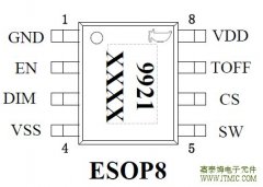 JTM9921 是一款高效率,稳
人气:201
JTM9921 是一款高效率,稳
人气:201
 The JTM3106 is a 380 KHz fixed
人气:197
The JTM3106 is a 380 KHz fixed
人气:197
 The JTM1483,JTM1483A is a synch
人气:190
The JTM1483,JTM1483A is a synch
人气:190
 The JTM3501 is a 150 KHz fixed
人气:190
The JTM3501 is a 150 KHz fixed
人气:190
 粤ICP备13004986号-3