|
六.电路原理图 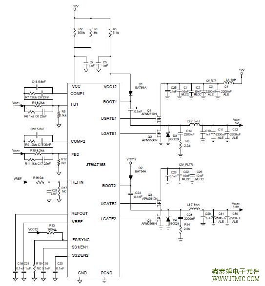 七,功能概述 Output Inductor Selection (Cont.) Where Fs is the switching frequency of the regulator. Al-though increase the inductor value and frequency reduce the ripple current and voltage, but there is a tradeoff ex-ists between the inductor’s ripple current and the regula-tor load transient response time.A smaller inductor will give the regulator a faster load transient response at the expense of higher ripple current.Increasing the switching frequency (FS) also reduces the ripple current and voltage, but it will increase the switch-ing loss of the MOSFET and the power dissipation of the converter. The maximum ripple current occurs at the maximum input voltage. A good starting point is to choose the ripple current to be approximately 30% of the maxi-mum output current.Once the inductance value has been chosen, select an inductor that is capable of carrying the required peak cur-rent without going into saturation. In some types of inductors, especially core that is made of ferrite, the ripple current will increase abruptly when it saturates. This will result in a larger output ripple voltage. Output Capacitor Selection Higher Capacitor value and lower ESR reduce the output ripple and the load transient drop. Therefore select high performance low ESR capacitors that are intended for switching regulator applications. In some applications, multiple capacitors have to be parallel to achieve the de-sired ESR value. A small decoupling capacitor in parallel for bypassing the noise is also recommended, and the voltage rating of the output capacitors are also must be considered. If tantalum capacitors are used, make sure they are surge tested by the manufactures. If in doubt, consult the capacitors manufacturer. Input Capacitor Selection The input capacitor is chosen based on the voltage rating and the RMS current rating. For reliable operation, select the capacitor voltage rating to be at least 1.3 times higher than the maximum input voltage. The maximum RMS current rating requirement is approxi-mately IOUT/2, where IOUT is the load current. During power up, the input capacitors have to handle large amount of surge current. If tantalum capacitors are used, make sure they are surge tested by the manufactures. If in doubt, consult the capacitors manufacturer. For high frequency decoupling, a ceramic capacitor 1uF can be connected between the drain of upper MOSFET and the source of lower MOSFET. MOSFET Selection The selection of the N-channel power MOSFETs are de-termined by the RDS(ON), reverse transfer capacitance (CRSS) and maximum output current requirement. The losses in the MOSFETs have two components: conduction loss and transition loss. For the upper and lower MOSFET, the losses are approximately given by the following : PUPPER=IOUT(1+TC)(RDS(ON))D+(0.5)(IOUT)(VIN)(tSW)FS PLOWER=IOUT(1+TC)(RDS(ON))(1-D) Where I is the load current OUT TC is the temperature dependency of RDS(ON) F is the switching frequency St is the switching interval sw D is the duty cycle Note that both MOSFETs have conduction losses while the upper MOSFET include an additional transition loss.The switching internal, tsw, is a function of the reverse transfer capacitance CRSS. The (1+TC) term is to factor in the temperature depen-dency of the RDS(ON) and can be extracted from the “RDS(ON) vs Temperature” curve of the power MOSFET. Short Circuit Protection The JTMA7158 provides a simple short circuit protection function, and it is not easy to predict its performance, since many factors can affect how well it works. Therefore, the limitations and suggestions of this method must be pro- vided for users to understand how to work it well.The short circuit protection was not designed to work for the output in initial short condition. In this case, the short circuit protection may not work, and damage the MOSFETs. If the circuit still works, remove the short can cause an inductive kick on the phase pin, and it may damage the IC and MOSFETs. If the resistance of the short is not low enough to cause protection, the regulator will work as the load has (责任编辑:oumao18) |

 粤ICP备13004986号-3