


目录
一,产品概述(General Description)
The JTM8203 is a highly advanced complete constant-current constant voltage linear charger for cell lithium-ion batteries. Its package and low external component count make the JTM8203 ideally suited for portable applications.
The charge current can be programmed externally with a single resistor, which may be programmed up to 1A. JTM8203 determines the charge mode by detecting the battery voltage: Pre-charge,constant current charging, constant voltage charging. The charge current of 0pre-charging and constant –current charging is adjustable.
The JTM8203 is monitored by temperature monitor during the constant-current
and constant-voltage charging. There are two LEDs indicate the charge mode.
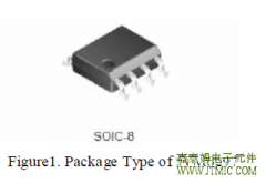
The JTM8203 is available in the SOP-8L package.
二.产品特点(Features)
1.)Preset 8.4V Charge Voltage with 1%Accuracy
2.)Programmable Charge Current Up to 1A
3.)Input Voltage:9-10V DC
4.)Pre-Charging, the Charge Current is adjustable
5.)Ideal for Dual-Cell 8.4V Li-Ion Batteries
6.)Constant -Current Charging, the Charge Current is adjustable
7.)Constant-Voltage Charging
8.)Constant-Current/Constant-Voltage
9.)Charging with Temperature Monitoring
10.)Automatic Recharge
11.)Double LEDs Charge Status Indication
三,应用范围 (Applications)
Charger for Li-Ion Coin Cell Batteries
Bluetooth Applications
Portable MP3 Players, Wireless Headsets
四.下载产品资料PDF文档
 |
jtm8203 |
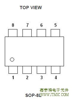
五,产品封装图 (Package)
|
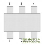
PIN NUMBER SOP-8L |
PIN NAME | DESCRIPTION |
| 1 | VIN | Positive Input Supply Voltage. |
| 2 | TS | Temperature Sense |
| 3 | CHRG |
Open-Drain Charge Status Output |
| 4 | GND | Ground |
| 5 | VOUT | Charge Current Output |
| 6 | EN | ON/OFF Control High Enable |
| 7 | CS | Charge Current Program |
| 8 | BATT | Battery Connection |
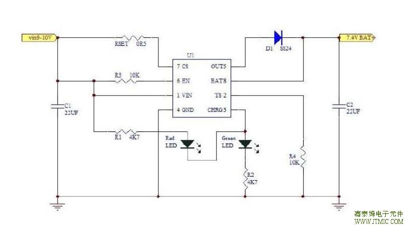
六.电路原理图
七,功能概述
Current Regulation Phase
The JTM8203 regulates current while the battery-pack voltage is less than the regulation voltage, VO(REG).
The JTM8203 monitors charge current at the CS input by the voltage drop across a sense-resistor, RSET,
in series with the battery pack. In current sensing configuration, RSET is between the VIN and CS pins,
charge-current feedback, applied through pin CS, maintains a voltage of VCS across the current sense
resistor. The following formula calculates the value of the Sense resistor:
Where IO(REG) is the desired charging current.
Voltage Phase
The voltage regulation feedback is through the BAT pin. This input is tied directly to the positive side of
the battery pack. The JTM8203 monitors the battery-pack voltage between the BAT and GND pins. The
JTM8203 is offered 8.4V output voltage.
Charge Termination Recharge
The JTM8203 monitors the charging current during the voltage-regulation phase. The JTM8203 declares a
done condition and terminates charge when the current drops to the charge termination threshold, ITERM.
A new charge cycle begins when the battery voltage falls below the VRCH threshold.
Battery Temperature Monitoring
A negative temperature coefficient (NTC) thermistor located close to the battery pack can be used to
monitor battery temperature and will not allow charging unless the battery temperature is within an
acceptable range.
Connect a 10k
thermistor from the TS pin to ground. With the 85µA pull-up current source, the hot
thermistor from the TS pin to ground. With the 85µA pull-up current source, the hot
temperature voltage threshold is 485mV. For cold temperature, the voltage threshold is set at 2.486V
with 85µA of pull-up current. The charge cycle begins or resumes once the temperature is within the
acceptable range.
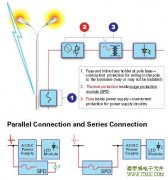
Reverse Blocking Protection
The optional reverse-blocking protection diode, depicted in Figure1 provides protection from a faulted or
shorted input, or from a reversed-polarity input source. Without the protection diode, a faulted of shorted
input would discharge the battery pack through the body diode of the external pass transistor.
If a reverse-protection diode is incorporated in the design, it should be chosen to handle the fast charge
current continuously at the maximum ambient temperature. In addition, the reverse-leakage current of
the diode should be kept as small as possible.
Selecting Input Capacitor
In most applications, all that is high-frequency decoupling capacitor. The JTM8203 works with both
regulated an unregulated external dc supplies. If a non-regulated supply is chosen, the supply voltage to
the minimum required input voltage at maximum load. If not, more capacitance must be added to the
input of the charger.
Selecting Output Capacitor
The JTM8203 does not require any output capacitor for loop stability.
In order to maintain good AC stability in constant Voltage mode, a minimum capacitance of 10uF is
recommenced to bypass the BAT pin to GND. This capacitance provides compensation when there is
no battery load. In addition, the battery and interconnections appear inductive at high frequencies.
These elements are in the control feedback loop during Constant Voltage mode. Therefore, the bypass
capacitance may be necessary to compensate for the inductive nature of the battery pack.
Virtually any good quality output filter capacitor can be used, independent of the capacitor’s minimum
ESR (Effective Series Resistance) value. The actual value of the capacitor and its associated ESR
depends on the forward transconductance (gm) and capacitance of the external pass transistor. A 10uF
tantalum or aluminum electrolytic capacitor at the output is usually sufficient to ensure stability for up to
a 1A output current.
八,相关产品
| 2节锂电充电IC | |||||||||
| 型号 | 电池数量 | 工作模式 | 工作电压 | 最大 | 工作电流 | 恒流恒压 | 输出电压 | 开关频率 | 封装 |
| 充电电流 | 精度 | ||||||||
| JTM8203 | 两节 | 线性,内置MOS | 9V-16V | 1A | 0.26mA | 1% | 8.4V | SOP-8L | |
| JTM8202 | 两节 | 开关式,内置MOS | 9V-16V | 2A | 0.26mA | 1% | 8.4V | 780KHz | SOP-8L |
| JTM8207 | 两节 | 开关式,外置MOS | 8.9V-20V | 2A | 3.5mA | 1% | 8.4V | 500KHz | SOP-8L |
| JTM4060 | 单节/两节 | 开关式,外置MOS | 最大20V | 3A | 1% | 4.2V/CELL | 600KHz | MSOP-10 | |
| JTM4061 | 单节/两节 | 开关式,外置MOS | 4.5V-12V | 2A | 5mA | 1% | 4.175V/CELL | 400KHz | TSSOP-14 |
| JTM4062 | 两节 | 开关式,外置MOS | 7.5V-28V | 5A | 1.55mA | 1% | 8.4V | 300KHz | TSSOP-16 |
| 多节锂电充电IC | |||||||||
| 型号 | 电池数量 | 工作模式 | 工作电压 | 最大 | 工作电流 | 恒流恒压 | 输出电压 | 开关频率 | 封装 |
| 充电电流 | 精度 | ||||||||
| JTM4063 | 三节 | 开关式,外置MOS | 7.5V-28V | 5A | 1.75mA | 1% | 12.6V | 300KHz | TSSOP-16 |
| JTM4064 | 四节 | 开关式,外置MOS | 7.5V-28V | 5A | 1.95mA | 1% | 16.8V | 300KHz | TSSOP-16 |
| JTM4065 | 1-6节可设置 | 开关式,外置MOS | 7.5V-28V | 5A | 1.7mA | 1% | 可调 | 300KHz | TSSOP-16 |
| 型号 | 输入电压 | 最大充电电流 | 充电类型 | 单节截止电压 | 封装形式 | ||||
| JTM4058 | 2.6-7.5V | 250mA | 1到8节镍镉/镍氢电池充电IC | 1.35V | SOP-8 | ||||
| JTM4059 | 2.3-6.5V | 1.2A | 1到3节镍镉/镍氢/镍锌电池充电IC | 1.35V | ESOP8 | ||||
| JTM4059B | 3.1-6.5V | 1A | 1到4节镍镉/镍氢电池充电IC | 1.35V | ESOP8 | ||||
| JTM4068 | 7.5-28V | 扩流5A | 2-17节镍氢电池充电IC | 1.35V | TSSOP16 | ||||
| JTM4067 | 7.5-28V | 扩流5A | 单节/多节铅酸电池充电IC | 3.6V | TSSOP16 | ||||
| 型号 | 输入耐压 | 检测电压范围 | 检测电 | 输出形式 | 工作电流 | 封装 | 直接替代型号 | ||
| 压精度 | |||||||||
| JTM61C/NXX2 | 12V | 1.1/1.8/2.0/2.1/2.2/2.4/2.5/ | 2% | CMOS/N沟道 | 1.1uA | SOT-23 | XC61FC(N)/XC61CC(N)/ | ||
| 2.7/2.8/3.0/3.3/3.5/3.6/ | RT9808/RT9809/AIC1680/ | ||||||||
| 3.9/4.0/4.2/4.4/5.0V | AP8822/S808/UT81XX | ||||||||
| JTM70XX | 12V | 1.1/1.8/2.0/2.1/2.2/2.4/2.5/ | 2% | CMOS/N沟道 | 1.1uA | SOT-23 | HT70XX/KIA70XX | ||
| 2.7/2.8/3.0/3.3/3.5/3.6/ | SOT-89 | ||||||||
| 3.9/4.0/4.2/4.4/5.0V | TO-92 | ||||||||
| JTM6100 | 6.5V | 1.2V以上,可以设置 | 2% | CMOS | 1.8uA | SOT-25 | |||
| JTM809系列 | 6V | 2.63V/2.93V/3.08V/ | 1% | CMOS | 1.0uA | SOT-23 | MAX809/ | ||
| 4.00V/4.38V/4.63V | IMP809/AME8500 | ||||||||
| JTM810系列 | 6V | 2.63V/2.93V/3.08V/ | 2% | CMOS | 8.0uA | SOT-23 | MAX810/IMP810 | ||
| 4.38V/4.63V | |||||||||
| JTM811系列 | 6V | 2.93V/4.00V/ | 2% | CMOS | 8.0uA | SOT-143 | MAX811/IMP811 | ||
| 4.38V/4.63V | |||||||||
| 我司的JTM61C/NXXXMR/SOT-23有如下优点: | |||||||||
| 1.耐压可达12V | |||||||||
| 2.静态电流小,只有1uA(典型值). | |||||||||
| 3.输出方式有N沟道和CMOS 2种. | |||||||||
| 4.输出检测电压值范围广,从1.1V~5.0V可以定义各电压值, | |||||||||
| 可以每隔0.1V定制. | |||||||||
| 5.目前检测电压有1.1/1.8/2.0/2.2/2.4/2.5/2.7/2.8/3.0/3.3/3.5/3.6/3.9/4.0/4.2/4.4V | |||||||||
| 6.封装采用金线,全测产品,一致性好,品质稳定. | |||||||||
| 我司的JTM70XXMR/PR SOT-23/SOT-89有如下优点: | |||||||||
| 1.耐压可达12V | |||||||||
| 2.静态电流小,只有1uA(典型值). | |||||||||
| 3.输出方式是N沟道输出. | |||||||||
| 4.输出检测电压值范围广,从1.1V~5.0V可以定义各电压值, | |||||||||
| 可以每隔0.1V定制. | |||||||||
| 5.目前检测电压有1.1/1.8/2.0/2.2/2.4/2.5/2.7/2.8/3.0/3.3/3.5/3.6/3.9/4.0/4.2/4.4V | |||||||||
| 6.封装采用金线,全测产品,一致性好,品质稳定. | |||||||||
 JTM4103是一款降压恒流型
人气:255
JTM4103是一款降压恒流型
人气:255
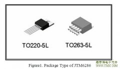 JTM6286,JTM6285 采用 60V 高压
人气:213
JTM6286,JTM6285 采用 60V 高压
人气:213
 The JTM6297,JTM6298,JTM6299 reg
人气:210
The JTM6297,JTM6298,JTM6299 reg
人气:210
 外驱MOSOS管,PSR控制模式,
人气:208
外驱MOSOS管,PSR控制模式,
人气:208
 The JTM1542 is a compact, high
人气:207
The JTM1542 is a compact, high
人气:207
 户外LED照明解决方案,通过
人气:204
户外LED照明解决方案,通过
人气:204
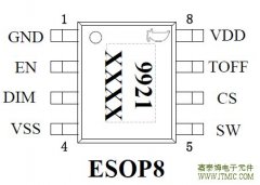 JTM9921 是一款高效率,稳
人气:201
JTM9921 是一款高效率,稳
人气:201
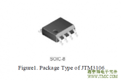 The JTM3106 is a 380 KHz fixed
人气:197
The JTM3106 is a 380 KHz fixed
人气:197
 The JTM1483,JTM1483A is a synch
人气:190
The JTM1483,JTM1483A is a synch
人气:190
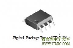 The JTM3501 is a 150 KHz fixed
人气:190
The JTM3501 is a 150 KHz fixed
人气:190
 粤ICP备13004986号-3